Description
Nominated for a Craftsmanship Award: AIA Kansas City, 2015.
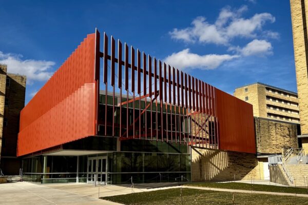
When the architecture firm of Helix was asked to work on the historic Baltimore Club, they probably jumped at the opportunity because of their love for old buildings.
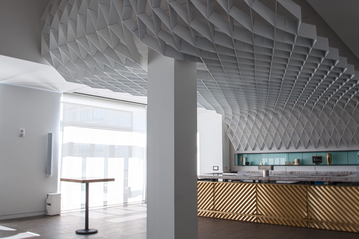
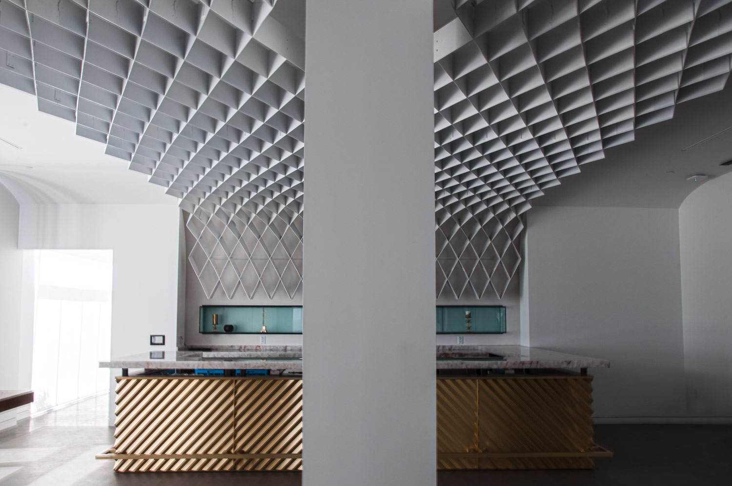
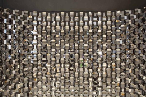
This 15-story building, built in 1920, was originally created as the home to a private gentlemen’s club that was established back in 1882. Appearing on the National Register of Historic Places, the building’s exterior is an example of gothic Tudor detailing and old-world craftsmanship. The interior showcases the original hand-hewn walnut, carved stone, ornate plaster and a new metal trellis that was inspired by the original plaster ceiling. That is where SSM and our partner 3 Axis came in to the picture.
3 Axis served as project coordinator while SSM engineered and fabricated the custom-designed trellis sculpture from 3/16” aluminum plate.
Before we begin, to describe our process, in order to ensure all parties were talking about the same thing, we used the following terms to define the parts and pieces that we would be dealing with:
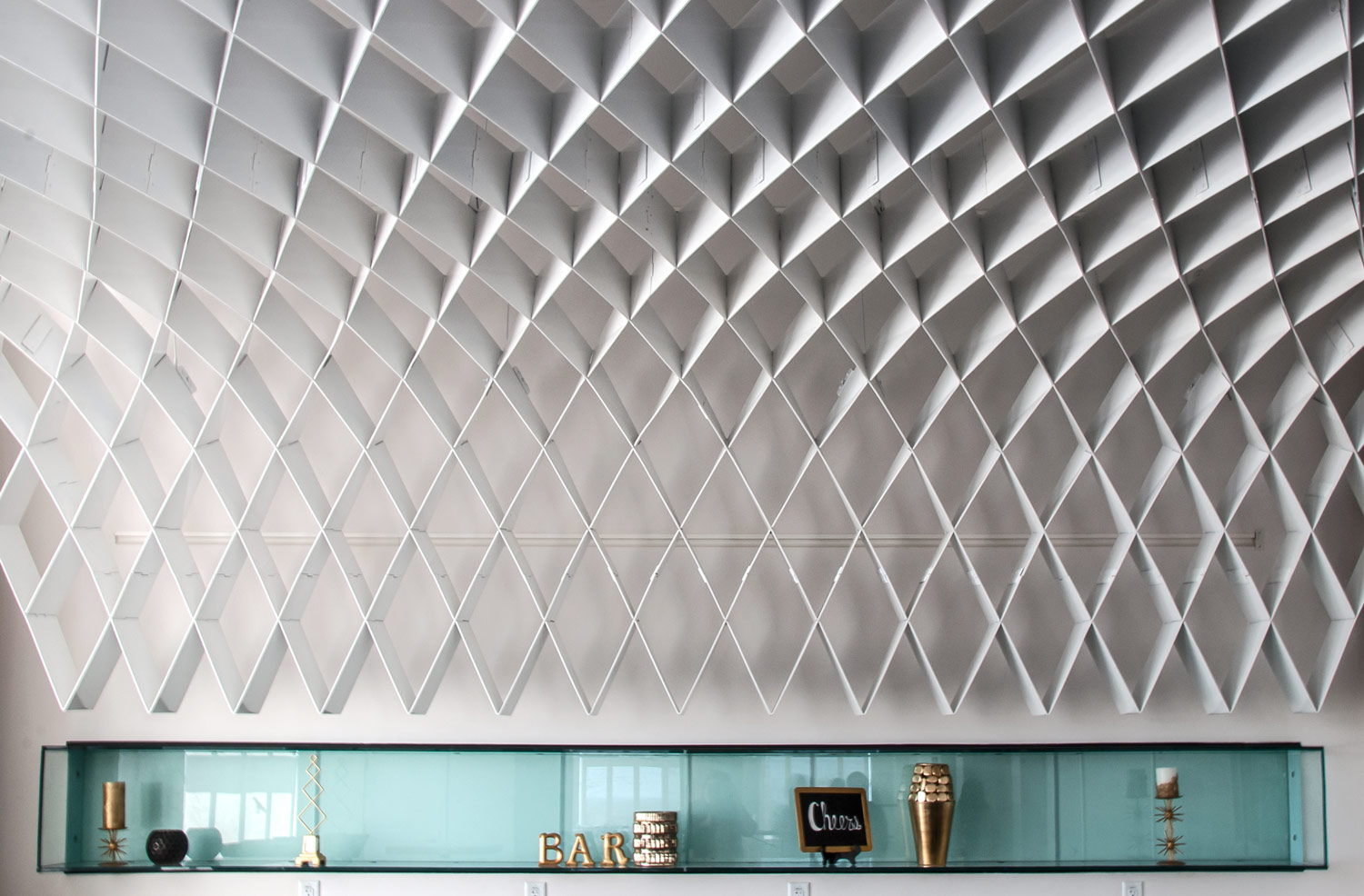
- fin = the trellis’ main components.
- x or y axis = the two primary directions the fin components extend.
- intersection = the point where two fins cross the same point in 3D space.
- joint = the method of interlocking one fin to the other.
- segment = the component of the trellis between fin intersections.
- module = a group of fins that define a specific area.
- plate = the 3/16” thick aluminum goods that the fins were to be cut from.
- material = aluminum.
- key = a fin to fin connection that prevents the two components from being joined together incorrectly.
- splice plate = the point where to fin’s keys interlock.
- stiffener = small corner brackets, bent to a specific angle, that help the trellis maintain shape.
- flat = the middle modules that are relatively flat in relationship to the floor.
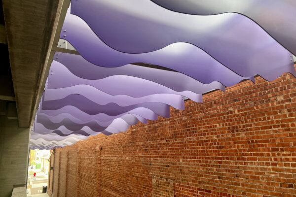
- droop = the end of the trellis that curves down to the bar.
- swoop = the end of the trellis that curves up into the higher ceiling area.
Our approach was as follows:
Starting with Helix’s Revit model, SSM broke the sculpture down into the various components to examine the 3D information from each part. The model was then separated into the various forms: swoop, droop & flat components.
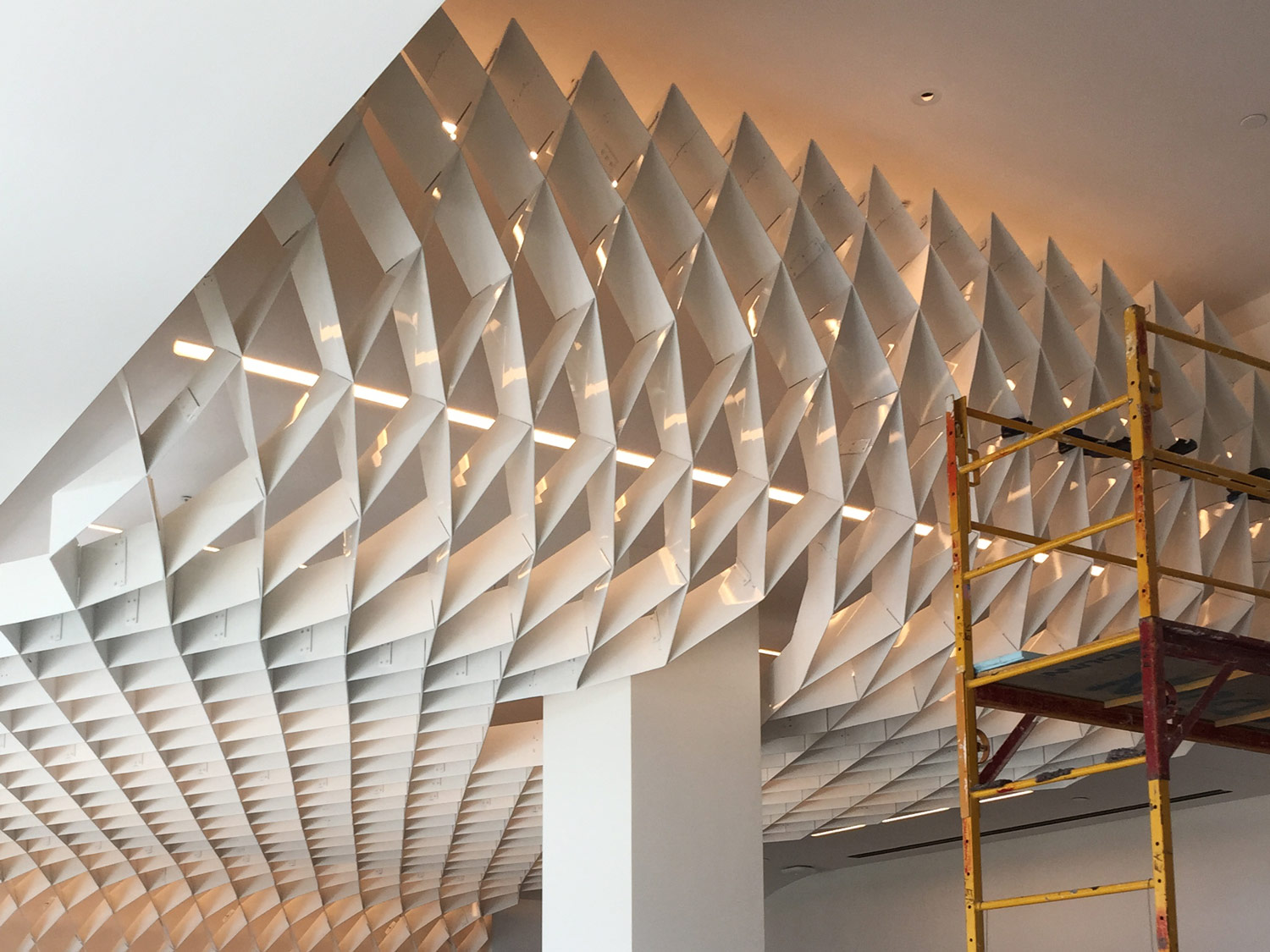
Each component was taken further down into segments and each segment was then flattened to create the master “fin” template. As the fin moves from “flat” to either the “droop” or the “swoop” areas, the fin has to rotate or twist. Due to that twist, the components that we “see” in the model are distorted and they are not viewable in true elevation as they move through the twisting areas.
In order to cut the fin components from flat aluminum plates, it was necessary to “flatten” the model. As the model contained some artifacts that produced false dimension, it became necessary to make adjustments to the flattened fins so that a consistent plan view dimension was read across the entirety of each fin component.
We created two plan views of the trellis, one for each directional axis, and the corresponding fin components were placed in relationship to their respective position.
The overall plan views were then subdivided into modules. The modular approach was necessary in order to get the components into the building due to the limitations of the elevator we were going to be allowed to use.
The modules also helped to determine where the trellis was to be supported. Each module needed to have at least four connection points so that the load [weight] would be equally distributed
Each individual fin was then broken down to relate to the module size. Component sizes were compared to that of the flat plate materials being used to cut parts from. Some fin components had to be subdivided due to proximity of module joints or due to their overall length being greater than the material’s.
Individual parts were then nested together, based upon the material plate size, in order to maximize the use of the materials and minimize waste. Once the fin parts were verified as being able to fit onto the plates, a “key” joint was added to lock the components together.
Many parts were location specific and could not be interchanged. Using our plan view layouts, coordinates were established along the X & Y axis to indicate segment, intersection & overall part number. That allowed us to use a “Battleship” [from the kid’s game of the same name] vocabulary to describe parts or location within the trellis.
Parts were then cut out utilizing our high speed punch press.